Compact Solar Water Heaters
Compact Solar Water Heaters 100, 125, 160 & 200
Thermosyphon Solar Water Heater Manufacturers – Compact Solar Heater
INNOVATION AND TECHNOLOGY IN COMPACT FORM
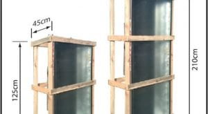
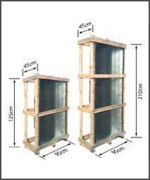
Convenient dimensions for easy transport and installation
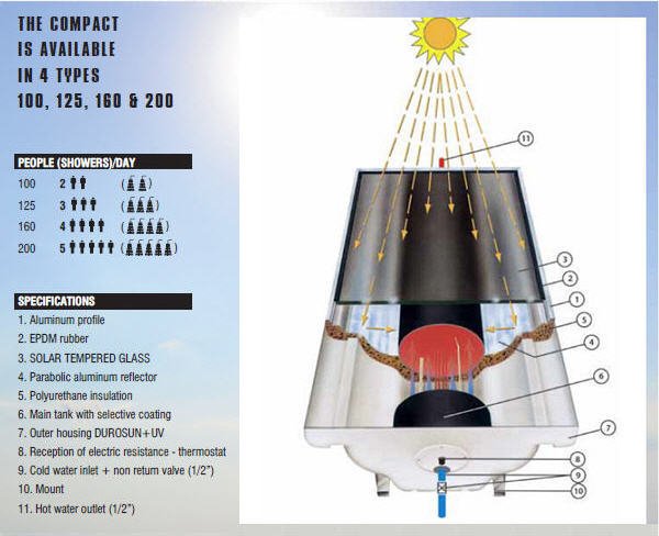
14 points of technological superiority
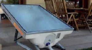
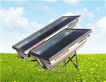
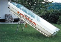
As the COMPACT uses natural circulation, it does not require any thermal fluids for the heat exchange, providing us thus with a 15% faster performance in comparison with other conventional solar water heaters. The parabolic shape of the COMPACT enables us to utilize the direct and indirect radiation, achieving thus high levels of thermal efficiency.
Taking into account that solar water heaters have become a real necessity, HELIOAKMI created the COMPACT in an affordable price for everyone.
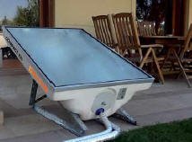
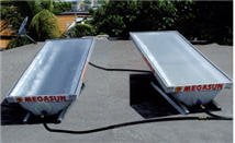
Τhe COMPACT does not require any expensive installation procedures, as it can be easily transported and installed on your terrace, roof or garden. It can be easily and rapidly connected even by an unskilled person, as it only contains one hot water inlet and one hot water outlet. However, the electrical connection must be done by a licensed electrician.
Since this is an open circuit, it does not require any extra addition of thermal fluids. If needed, a possible inspection or repair of the tank can be made even by an unskilled person. The only thing you need to do is to remove the profile with the unbreakable glass and unscrew the 4 nuts that secure the tank.
The large size of the tank and the even design of the COMPACT prevent the device from freezing, even in temperatures reaching the – 2°C .
As the more significant losses of the COMPACT take place during nighttime, you must adjust your needs of hot water during summer time till 12pm and during winter time till 10pm. If the amount of hot water in the morning during winter time is not sufficient, then you can activate the electical resistance.
Τhe COMPACT may be available with an extra heat exchanger (coil), upon request, and can be connected with the central heating system (radiator).


Τhe COMPACT is manufactured by HELIOAKMI, which over the past 40 years has been using the most cutting-edge scientific and technological expertise and had therefore managed to turn the Compact into the most revolutionary device.
And many, many more…
…COMPACT is an advanced answer to solar energy technology.
INSTALLATION INSTRUCTIONS COMPACT 100 - 125 - 160 - 200

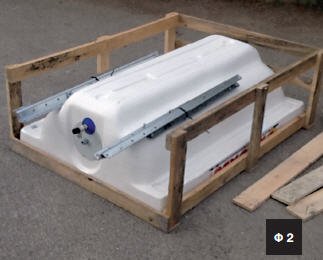
Place the COMPACT with the glass facing the floor.
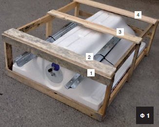
Remove the 4 horizontal wooden planks.
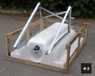
Create the 2 triangles and place the “Χ” plates of the mount by tightening all screws and nuts.
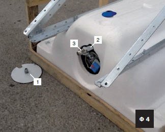
Remove the plastic cover (1) and screw the nipple fitting (2) and the safety valve (3). (Use Teflon to seal them).
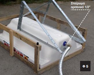
Connect the cold water inlet and hot water outlet (1/2” male thread). Use a 15Χ2.5mm plastic pipe. The unions that will connect the pipes with the device must have a 1/2” female thread. The plastic pipe that you will choose should be able to withstand temperatures up to 90°C and have a good tolerance at a pressure of 10 BAR.
Insulate properly the pipes with a suitable insulating material of at least 6 mm.

Lift the wooden box to an upright position, remove and place the device in such a way that the northern part faces the South and the southern part the North.
Connect the insulated pipes to the outlet and inlet of the device (1/2” male thread) and lead them to the place where they will be connected in order for you to be supplied with hot water at the desired place. Consult a plumber if you are not sure about the connections.
When first filling the device with cold water, the hot water outlet must be open (in order to let the air escape) until the device is completely filled.
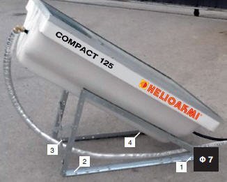
Securely fasten the device at the place where it will be installed and screw it (positions 1, 2, 3, 4, photograph 7) by using dowels and lag screws. Make sure that the place where the device will be installed has the right static strength and the appropriate containment in order for the product to be protected against strong winds and extreme weather conditions. (Consult your mechanic).
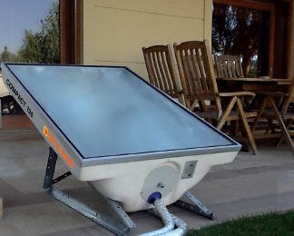
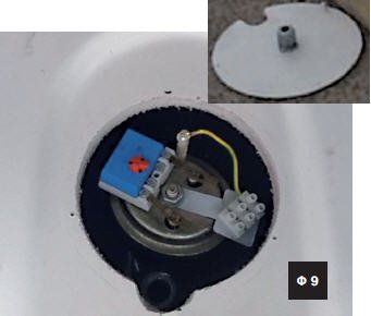
For the electrical connection of the device the plastic cover must be removed. The connection must be made by a licensed electrician following the instructions below.
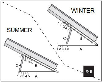
For the maximum performance of the device the vertical plates C should be connected to the positions 1A & 1B during the summer time (April – September) and during the winter time (October – March) to the positions 5A & 5B respectively
CAUTION : The company bears no responsibility for incomplete or improper installation of the device or for any damages that may be caused because of that to device or to third parties. We advise you to get an insurance against civil liability.
DESCRIPTION OF THE ELECTRICAL RESISTANCE AND THE THERMOSTAT

21 Plastic cover
22 Electrical resistance
22Α Thermostat position
22Β Resistance lid
23 Mount of power supply
line connector
24 Metal conductors for the connection
of the resistance with the
thermostat
25 Rubber flange for sealing
26 Central nut
27 Tightening nuts
28 Earthing terminal
29 Electrical resistance connector
30 Earthing conductor
31 Electrical conductors
32 Power supply line connector
33 Thermostat
34 Thermoregulator
35 Thermal safety switch
(indication “F” of “S”)
CABLE CONNECTION INSTRUCTIONS


1. Turn off the power supply.
2. The lid of the electrical
resistance is at the bottom of
the device. Unscrew the 4
screws and remove the lid (21).
3. The factory setting of the
thermostat is set at 60°C. You
can however, set the
temperature that you desire by
using the thermoregulator (34).
In this case we strongly
recommend that the
temperature does not exceed
the 75°C.
4. Check the thermal safety switch
(indication “F” or “S”) which is
on the thermostat. The safety
switch (red button) is in
operation when pushed in.
5. Connect to the connector 2 of
the thermostat the connector
“N” of the power supply line
connector (blue cable). Connect
to the connector 3 of the
thermostat the connector “L” of
the power supply line connector
(black cable) (see figure).
6. The earthing conductor is
connected by the manufacturer
as shown in the figure. Make
sure that it is firmly screwed.
7. Pass the cable through the
hole of the lid (21) and connect
the cables on the power supply
line connector. Screw the lid 21
on the tank.
Caution
The earthing terminal ()
on the power supply line
connector must be connected
with the earthing terminal of the
building.
The power cord must be
connected to a switchboard of
minimum 3 mm distance
between the contacts.
8. The standard power of the
electric resistance is 4000W for
230V. Upon request an electric
resistance with power range
from 800W to 4000W can be
delivered. For 110V an electric
resistance with power range
from 800W to 2000W is
available (upon request).
Note
The electrical connections must
be made by a certified
electrician. Ensure that all electrical
connections comply with the
electrical regulations
applicable in your area and your
building. Do not turn on the electrical
resistance when the tank is
empty.
ELECTRICAL RESISTANCE WITH AN INTEGRATED EXCHANGER

All the devices 100, 125, 160 & 200 can be delivered, upon request with an integrated on the resistance.
The exchanger can be connected with the central heating system for greater economy.
The instructions of the electrical connections are the same as those of the electrical resistance without exchanger.
Global Recognition








FIRST PRIZE OF EXCELLENCE FROM THE MINISTRY OF DEVELOPMENT
